STEP-BY-STEP
Commercial Electrical Plans - The Basics
|
STEP 1
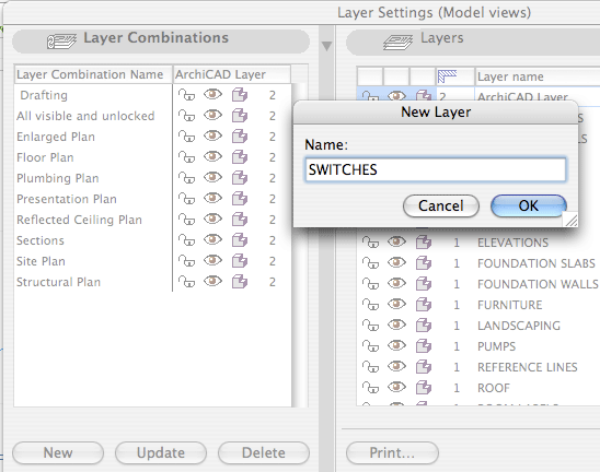 |
Begin by setting up 3 new LAYERS: Keep your symbols organized, it would also benefit the student to break the fixtures into even more layers. For example: |
|
STEP 2 OUTLETS Start by placing outlets in obvious locations. Make sure the wall is suitable for a typical duplex outlet, and when needed, add floor outlets or quad outlets. Heavy power needs will require 220 volt outlets, and exterior outlets would need to be waterproof. 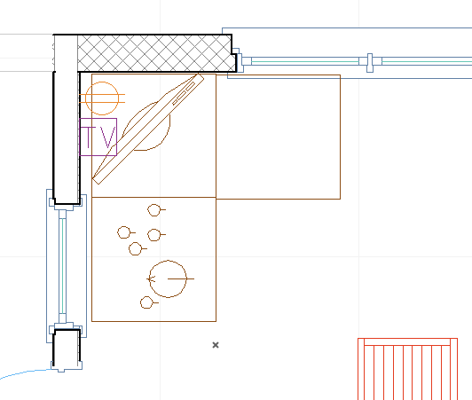 |
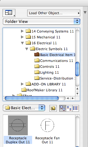
Standard outlets can be found in the object menu under 16 Electrical > Electric Symbols > Basic Electrical Items. Make sure to put the outlets in the outlet layer. |
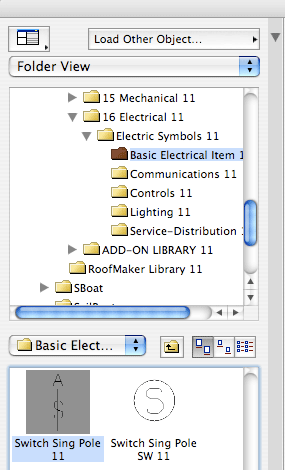
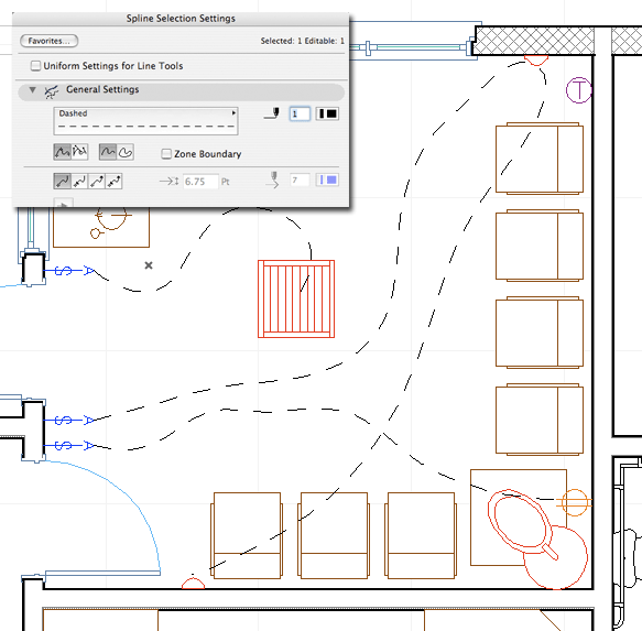
STEP 3 SWITCHES Next place switches to control your fixtures is required locations. Just inside the doorway is advisable. Single pole switches operate one fixture. Triple pole switches operate the same light from two different locations (top of the stairs and the bottom for example). Larger rooms will sometimes require a switch inside the doors at both ends. 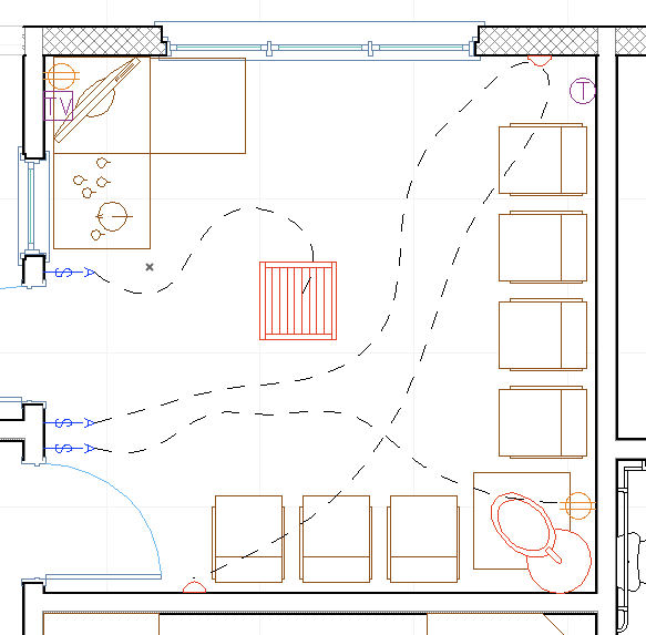 |
Put switches where they are safe. |
STEP 4 |
Make sure every room has some sort of light fixture inside. |
[Updated:
